

Lab Details
Lab Vendor: Cisco
Lab Name: Spanning-Tree Protocol
Lab Level: Beginner
Lab Published: Sept 30, 2026
Lab Author: Hind Networks
Lab Download
- Lab Topology
- Lab Workbook (.pdf)
- Lab Practical (Packet Tracer)
Absolutely. Since you already have the STP lab workbook, the theory should work as a professional introduction to the practical—not repeat the lab steps.
Here is a polished, website-ready version for Hind Networks.
Spanning Tree Protocol (STP)
Introduction
In a switched network, redundant links are often used to provide network availability and fault tolerance. However, when multiple switches are connected with redundant paths, Layer 2 networks can develop switching loops. These loops can cause serious network problems such as broadcast storms, MAC address instability, and duplicate frames.
The Spanning Tree Protocol (STP) was developed to prevent these Layer 2 loops while still allowing redundant physical connections between switches.
STP creates a loop-free logical topology by placing some redundant switch ports into a blocking state. If the active path fails, STP can recalculate the topology and allow a previously blocked path to become active.
Why Do We Need STP?
Ethernet switches forward frames based on their MAC address tables. Unlike routers, traditional Layer 2 switches do not use a TTL mechanism to automatically stop a frame from circulating indefinitely.
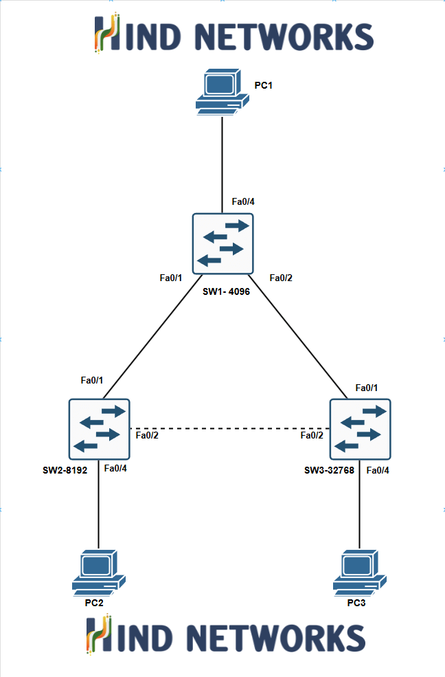
Consider a network where three switches are connected in a triangle:
Switch 1 → Switch 2 → Switch 3 → Switch 1
If a broadcast frame enters this topology, it can continue circulating between the switches. As the traffic increases, the network may experience a broadcast storm, consuming significant bandwidth and switch resources.
STP solves this problem by logically removing one of the redundant paths from the forwarding topology.
The physical connection remains available, but the selected port is placed into a non-forwarding state.
How STP Works
STP uses a series of steps to build a loop-free topology:
1. Root Bridge Election
STP first elects a Root Bridge. The Root Bridge becomes the reference point for calculating the spanning-tree topology.
The switch with the lowest Bridge ID is elected as the Root Bridge.
The Bridge ID is primarily determined by:
- Bridge Priority
- Extended System ID
- MAC Address
By default, all switches may have the same priority, so the MAC address can become the deciding factor.
2. Root Port Selection
After the Root Bridge is elected, every non-root switch selects one Root Port.
The Root Port is the port that provides the switch with the best path toward the Root Bridge.
Path selection considers factors such as:
- STP path cost
- Bridge ID
- Port ID
Each non-root switch normally has one Root Port for a given spanning-tree instance.
3. Designated Port Selection
STP also determines which port will be the Designated Port for each network segment.
The Designated Port is responsible for forwarding traffic toward that segment.
This ensures that each segment has a preferred forwarding path while preventing Layer 2 loops.
4. Blocking Redundant Paths
Any redundant path that is not selected for forwarding is placed into a non-forwarding state.
This is the key concept behind STP.
The redundant link is not physically disconnected. Instead, STP prevents it from forwarding normal data traffic until it is required.
If an active forwarding path fails, STP can recalculate the topology and potentially place the redundant path into forwarding operation.
STP Port Roles
Understanding STP port roles is important when troubleshooting a switched network.
Root Port
The Root Port provides the best path from a non-root switch toward the Root Bridge.
Designated Port
The Designated Port is selected to forward traffic for a particular network segment.
Non-Designated / Alternate Port
A redundant port that is not selected as the forwarding path may remain in a non-forwarding role, depending on the STP implementation and version.
STP Port States
Traditional IEEE 802.1D STP uses the following port states:
Blocking → Listening → Learning → Forwarding
A port may also enter the Disabled state when it is administratively or operationally disabled.
Blocking
The port does not forward normal data frames or learn MAC addresses. It can still receive STP information.
Listening
The switch begins participating in the STP topology calculation but does not yet forward user traffic.
Learning
The switch begins learning MAC addresses but does not yet forward normal data frames.
Forwarding
The port can forward and receive normal network traffic and learn MAC addresses.
BPDUs in STP
STP switches exchange Bridge Protocol Data Units (BPDUs) to communicate information about the spanning-tree topology.
BPDUs contain information that helps switches:
- Elect the Root Bridge
- Determine the best path to the Root Bridge
- Select Root and Designated Ports
- Detect topology changes
BPDUs are therefore an essential part of how STP maintains a loop-free Layer 2 topology.
STP Path Cost
STP uses path cost to determine the preferred path toward the Root Bridge.
Generally, a higher-speed link has a lower cost than a lower-speed link. Therefore, STP normally prefers a path with a lower total cost.
The exact cost values depend on the STP path-cost method being used.
When multiple paths are available, STP uses its selection rules to determine which path should forward traffic and which path should remain redundant.
Root Bridge Selection
The Root Bridge is selected using the lowest Bridge ID.
In a simplified form:
Bridge ID = Bridge Priority + Extended System ID + MAC Address
If two switches have the same relevant priority value, the switch with the lower MAC address can win the election.
For this reason, network administrators commonly configure the desired Root Bridge intentionally rather than allowing the election to depend only on MAC addresses.
Types of Spanning Tree Protocols
Several STP implementations and standards are commonly encountered in enterprise networks.
STP – IEEE 802.1D
The original Spanning Tree Protocol. It provides loop prevention but can take significant time to converge after a topology change.
RSTP – IEEE 802.1w
Rapid Spanning Tree Protocol improves convergence speed compared with traditional STP.
MSTP – IEEE 802.1s
Multiple Spanning Tree Protocol allows multiple VLANs to be mapped to spanning-tree instances, helping improve scalability in larger networks.
PVST+
Per-VLAN Spanning Tree Plus maintains a separate spanning-tree instance for each VLAN on supported Cisco networks.
STP and Redundancy
One of the most important concepts to understand is that STP does not eliminate physical redundancy.
Instead, it controls how that redundancy is used.
For example:
          SW1
         /   \
        /     \
      SW2-----SW3
The three switches provide physical redundancy, but forwarding traffic through all three links simultaneously could create a Layer 2 loop.
STP may place one of the redundant paths into a non-forwarding state:
          SW1
         /   \
        /     \
      SW2     SW3
        \     /
         \___/
       Blocked Path
If a forwarding link fails, STP can react to the topology change and make use of the redundant path.
STP Troubleshooting
When troubleshooting STP, network engineers commonly examine:
- Which switch is the Root Bridge
- Root Bridge priority
- Root Port on each non-root switch
- Designated Ports
- Blocked/alternate paths
- STP path cost
- Port priority
- VLAN-specific STP information
- BPDU information
- Topology changes
On Cisco switches, useful commands include:
show spanning-tree
show spanning-tree vlan <vlan-id>
show spanning-tree root
show spanning-tree detail
These commands help identify the current STP topology and determine why a particular port is forwarding or not forwarding.
Practical Lab
Understanding STP is much easier when the concepts are observed on an actual switch topology.
In the accompanying Spanning Tree Protocol lab workbook, you can practice STP concepts using a practical network topology and observe how switches:
- Elect the Root Bridge
- Select Root Ports
- Select Designated Ports
- Place redundant ports into a non-forwarding state
- Calculate the preferred path
- React to link failures
- Recalculate the spanning-tree topology
The lab is designed to connect the theoretical concepts of STP with real switch configurations and verification commands.
Key Takeaways
Spanning Tree Protocol (STP) is a fundamental Layer 2 technology used to prevent switching loops in Ethernet networks.
The key concepts to remember are:
Root Bridge → Root Port → Designated Port → Redundant/Blocked Path
STP allows network designers to maintain physical redundancy while preventing Layer 2 loops. Understanding Bridge ID, path cost, BPDUs, port roles, and port states is essential for anyone working with enterprise switching networks.
With the practical lab workbook, these concepts can be tested directly in a switch-based topology, making it easier to understand how STP behaves in real-world network scenarios.